|
The recorder affords rapid and precise response, memory and display of peak readings, remote sensing, recording flexibility and simplicity of operation. This compact, portable instrument offers advanced features previously unavailable in its price range. Features include:
|
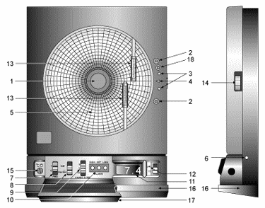
 Figure 1-1. Front and Side Views of the Recorder |
|
|
Item
|
DESCRIPTION
|
Function
|
|
1
|
Chart
Paper Knob (magnetic)
|
Holds chart paper in place. |
|
2
|
Light Bulbs
|
Lights up the paper in a dark room. Note that the bulbs function only when the recorder is powered by the 9Vdc adapter. |
|
3
|
Pen
Cap
|
3 Posts Holds the loose pen caps. |
|
4
|
Time Set Arrow
|
Helps align the time on the new chart paper with the actual time. |
|
5
|
Chart Paper
(double sided) |
Charts are available for 1, 7, and 32 day recording times. See the inside back cover for a detailed list of paper available. |
|
6
|
ac
Power Jack Allows
|
the unit to be powered from ac power using the ac adaptor (110Vac stepped down to 9Vdc) supplied. |
|
7
|
Power Switch
|
Selects Cal mode for pH sensor calibration, using the adjustments inside cover, or normal operation mode . |
|
8
|
Cal/Normal Mode Switch
|
Selects Cal mode for pH sensor calibration, using the adjustments inside cover, or normal operation mode . |
|
9
|
1/7/32 Day Mode Switch
|
Selects chart type: 1, 7, or 32 day operation. |
|
10
|
Alarm Display Buttons These buttons are accessible behind the control
panel door. (HIGH, SET, LOW)
|
High and Low buttons: 1. Selects and changes calibration codes. 2. Chooses the high/low alarm limit (for either ░C or pH). 3. Selects and changes the alarm limits. 4. Checks alarm limits in operating mode. 5. Low button only: when pressed during power up, disables the alarm function. Set button: 1. Activates calibration mode when pressed during power up. 2. Enters calibration codes in memory. 3. Activates alarm limits. 4. Enters alarm limits in memory. 5. Disables the sounding of the alarm (and activation of the relay) for 10 seconds. |
|
11
|
LCD Display
|
Displays temperature and pH values (depending on the setting of Display Selection Switch). |
|
12
|
Display Selection
|
Switch Allows the user to select display pH or fluid temperature in ░C . (Refer also to item #10). |
|
13
|
Pen Arm and Holder (2 each)
|
Holds and moves the pH and temperature pens. |
|
14
|
Latch Button
|
Releases and secures the recorderÆs door. |
|
15
|
Control
Panel Door
|
Lock Locks or unlocks the control panel door |
|
16
|
Decorative Foot Cover
|
Stays in place for wall-mounting the recorder. Removed for upright bench-top use. |
|
17
|
Control Panel Door
|
Covers the alarm display buttons (High, Set, and Low), power switch, 1/7/32 day mode switch, and Cal/Normal mode switch. |
|
18
|
Light Bulb
|
Push Button Turns the light bulbs on and off. |
|
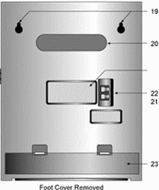
21
|
ôKeyholeö
Slot Mounting
|
Holes Allows the recorder to be mounted on the wall. |
|
22
|
Carrying
Slot
|
Allows the user to carry the recorder conveniently. |
|
23
|
Product
Label
|
Product information label. |
|
24
|
Alarm/Relay
Contacts
|
Allows the user to hook up an external, dry contact alarm to the recorder. |
|
25
|
Battery
Compartment
|
Holds 4 ôDö size batteries which provide power if the ac adaptor is not used, or with adapter, provide power backup in case of ac power failure. |
